Skip to content
Sat. Mar 14th, 2026
Retro Computer Shopper
all your retro computing and console needs
Home
Store
Store
Computers and Consoles
Store
/
Computers and Consoles
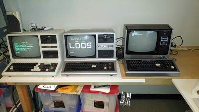
Classic Computers
Classic Computers
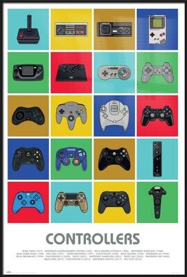
Classic Consoles
Classic Consoles
40 pin socket dual wipe
40 pin socket dual wipe
$3.00
Buy Now
You missed
Uncategorized
Welcome to Retro Computer Shopper
July 20, 2022
admin